Hello dear readers. Today we are writing about the design and development process for our new C6 Canards. So as to establish a baseline in order to help explain the story of this project, we’d like to make sure there are no misconceptions about what and how canards contribute to downforce.In Part 2, we'll discuss the production process-taking these digital files and transforming them into real products.
Canards (or Dive Planes) are not a panacea for front downforce. Canards have a specific function and the misuse or misunderstanding of their correct function will slow your race car- perhaps you bolted on a set and have found no difference in handling, or perhaps a detrimental effect, or perhaps you’ve tricked yourself into believing they have been working, or maybe they’ve been exactly what you’ve needed.
1.Why use canards?
If you need more front downforce
2.When to use canards?
If you already have a splitter and it doesn’t produce enough downforce for your needs, or if you are unable to use a more effective splitter
The important part is that you must have a splitter for most canards to work effectively. There are a few exceptions to this rule, and side benefits to certain canard designs and their placement. In some cases, we’ve even found designs that do not increase downforce, but do decrease drag.
There is a good deal of information on the general application of canards (more on that below), but for this post I’d like to focus on our development process for the C6 Project.
At RHR, and previously AJ Hartman Racing, we’ve sold many canards, and we expect to continue to do so in the future. To improve our offerings and differentiate us from manufacturers that sell triangular bits of carbon that seem randomly attached to the car, we’ve recently engaged our favorite aerodynamicist, JKF, to design canards for the C6 Corvette with a specific rule set in mind and certain design goals.
We are not positive, but short of WTAC and Professional (GT3/GT4, etc.) cars, we are aware of a manufacturer that has committed to this level of effort and expense for something as small and inexpensive as a canard.
The C6 project had two objectives:
Design one very efficient low drag canard package, and one maximum downforce canard set. Both had to fit within NASA’s ST/TT rules, which mandates that an aerodynamic device may not extend 6” beyond the furthest point of the side of the bodywork in a vertical plane.
Further design constraints included the use of single elements for the low drag set (to produce and sell them at relatively low cost) while the high downforce versions could be airfoils- that is, they are 3D winglets.
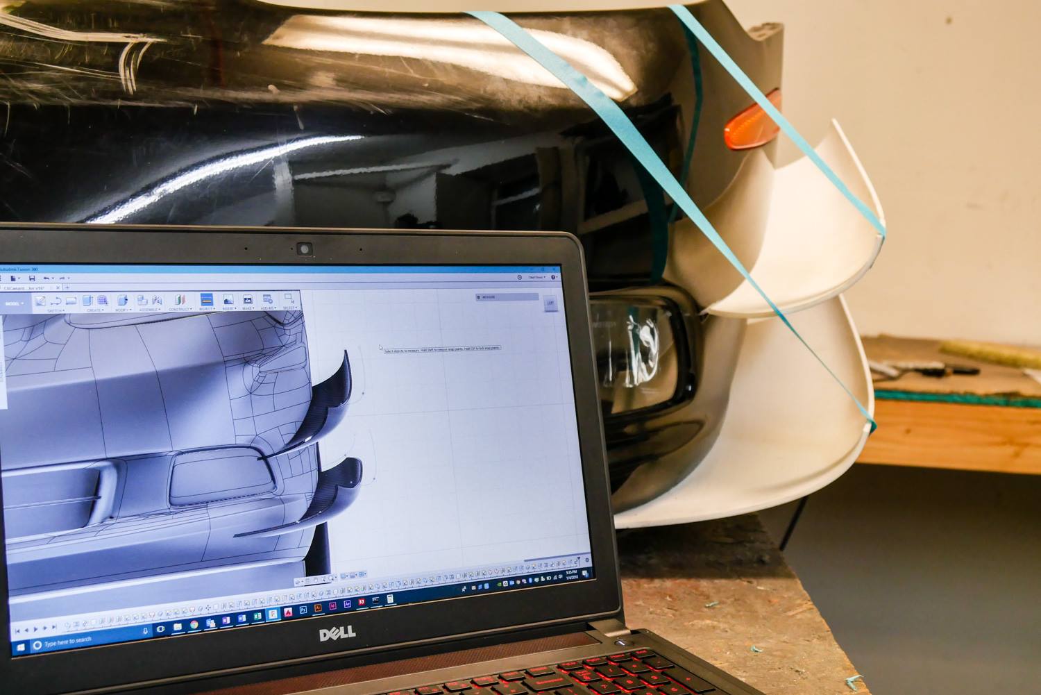
To start the process we purchased the solid 3D model of the C6 corvette as well as a used C6 bumper from eBay.
fig.1 LD Iteration 2 3D printed mockups on Bay bumper
Our design cycle with JKF took some ramp up time- We had to adopt a 3D CAD program (Fusion 360), a data analysis and visualization package (Paraview), meshing software (Netgen) file collaboration (Google Drive) and many emails, Google hangouts, screenshares, and since I happened to be in Sydney one day on a business trip, a great discussion over a Sushi lunch.
While Kyle does industrial strength aerodynamics on his own customized clustered analysis platform, we run the models through Autodesk Simulation CFD to see results for ourselves (for which he laughs at us). One of us has a PhD. in Aerodynamics, and it’s not AJ nor Olaaf.
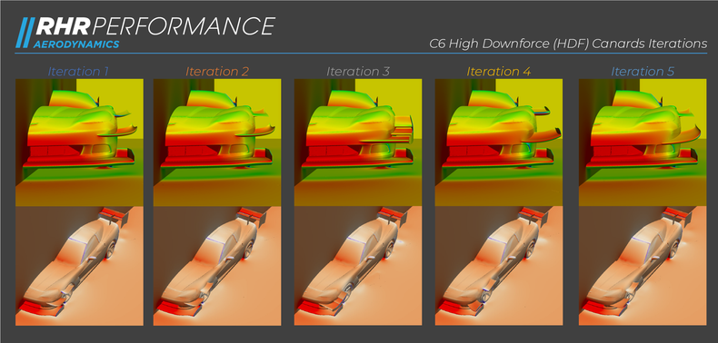
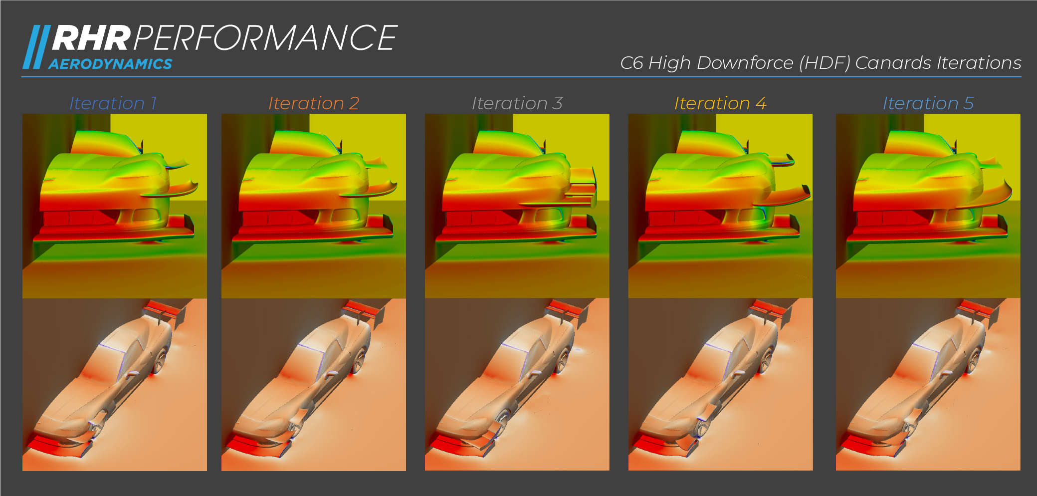
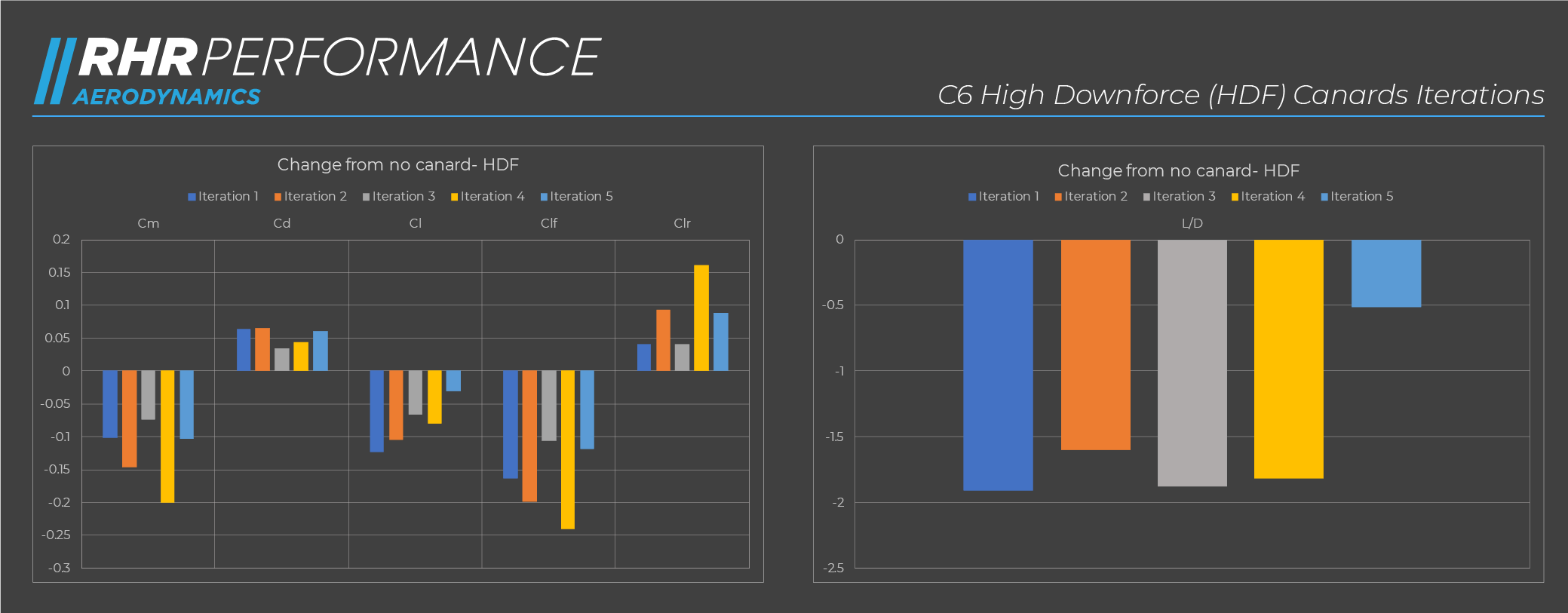
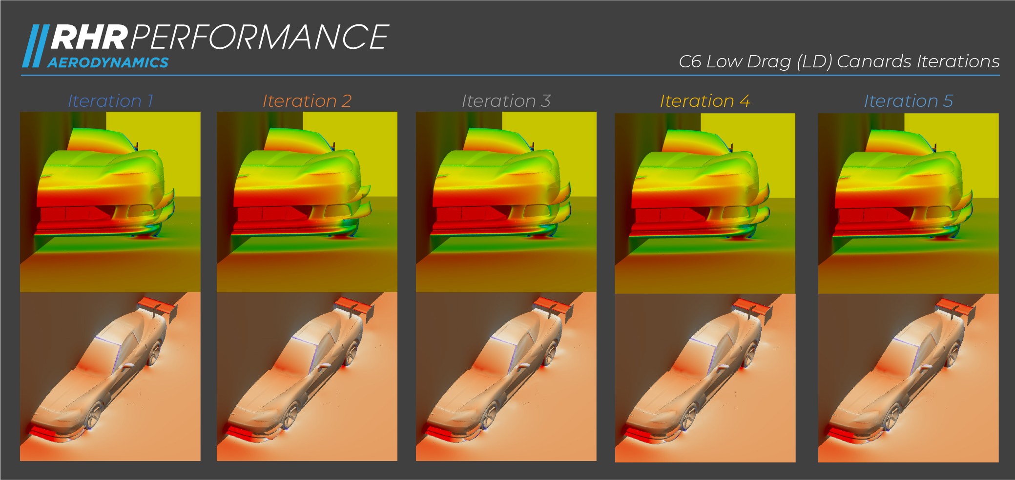
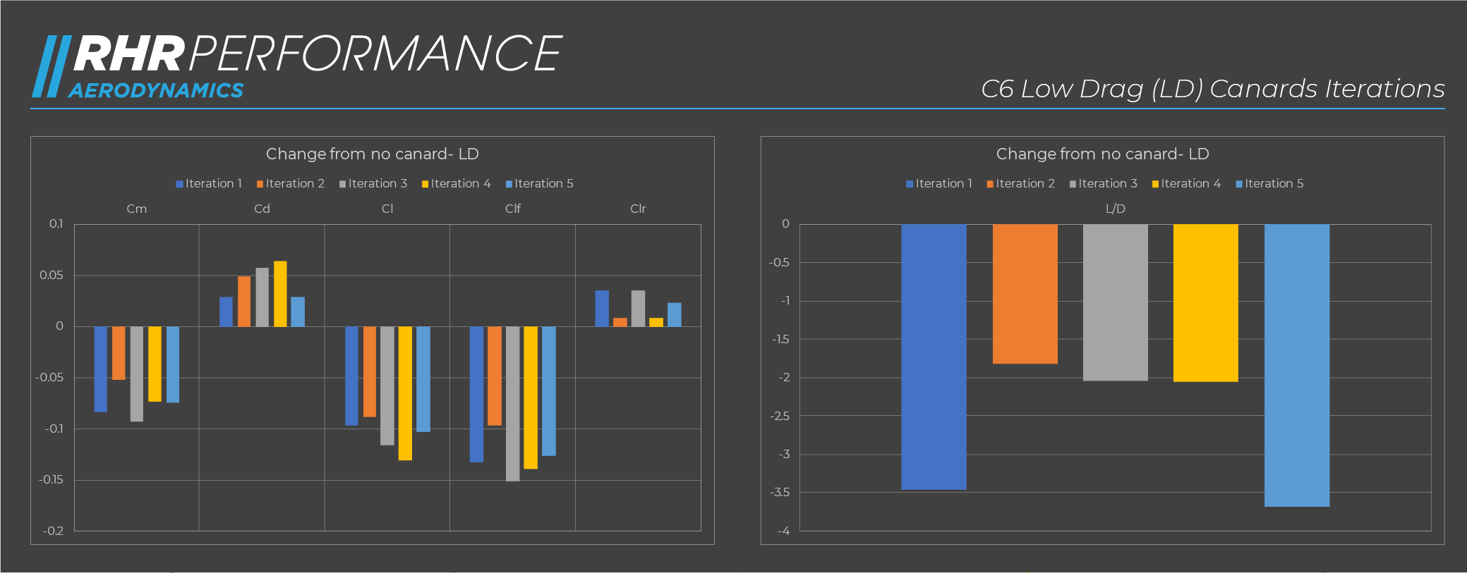
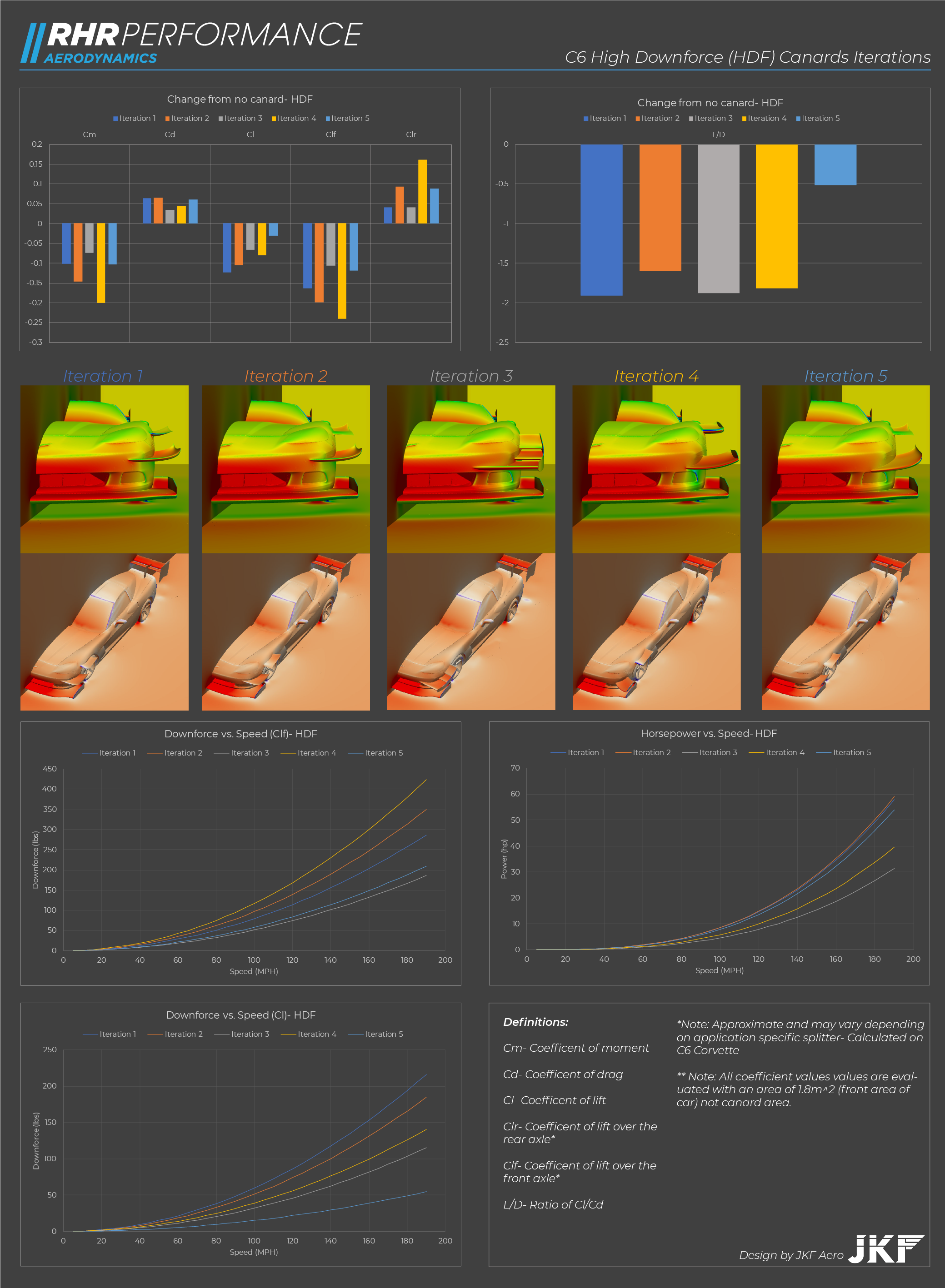
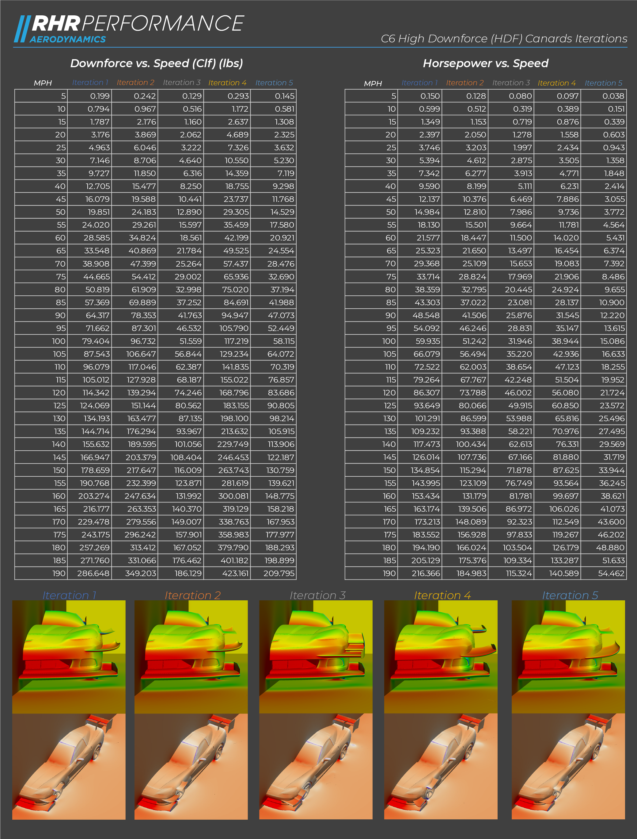
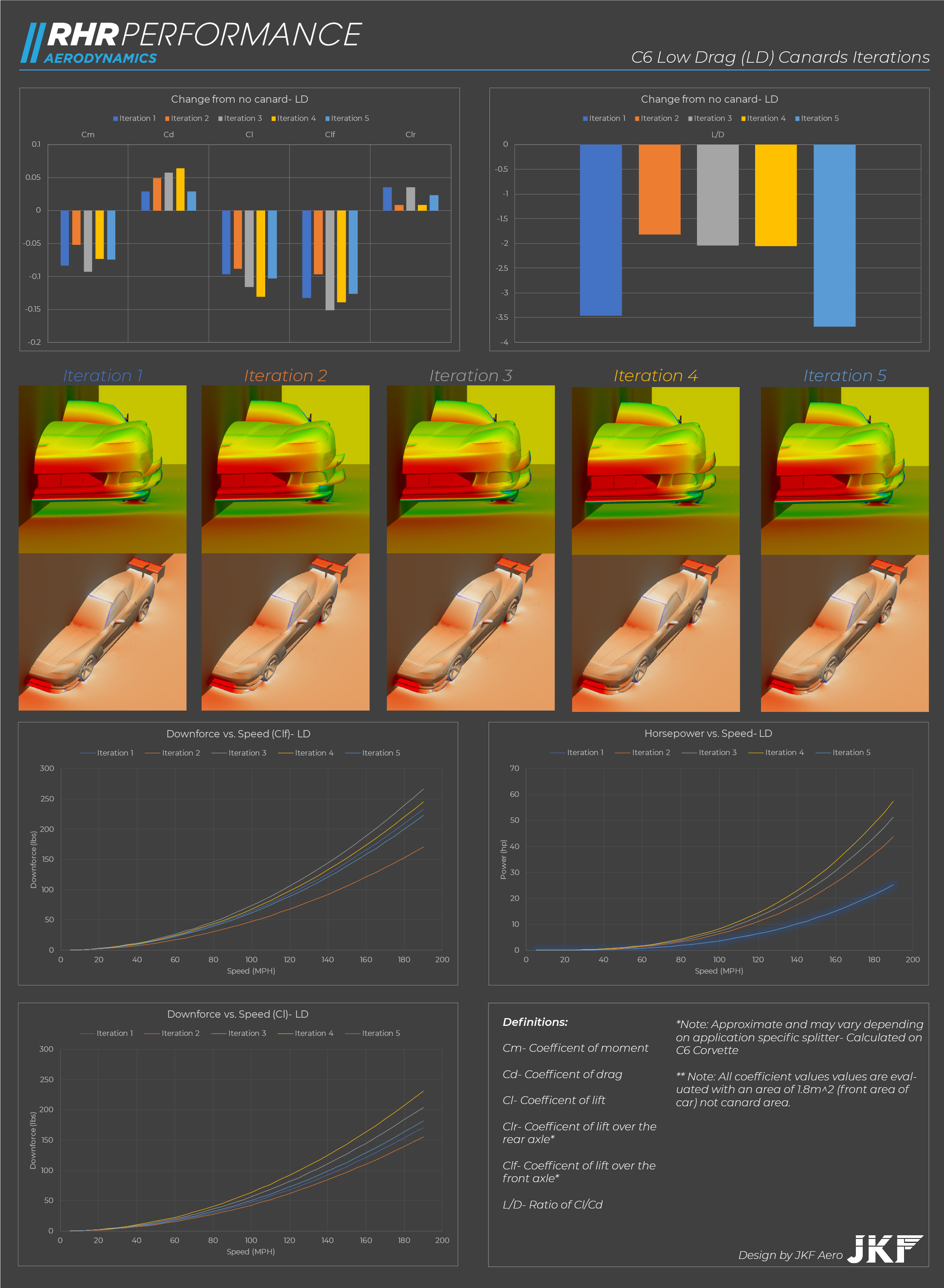
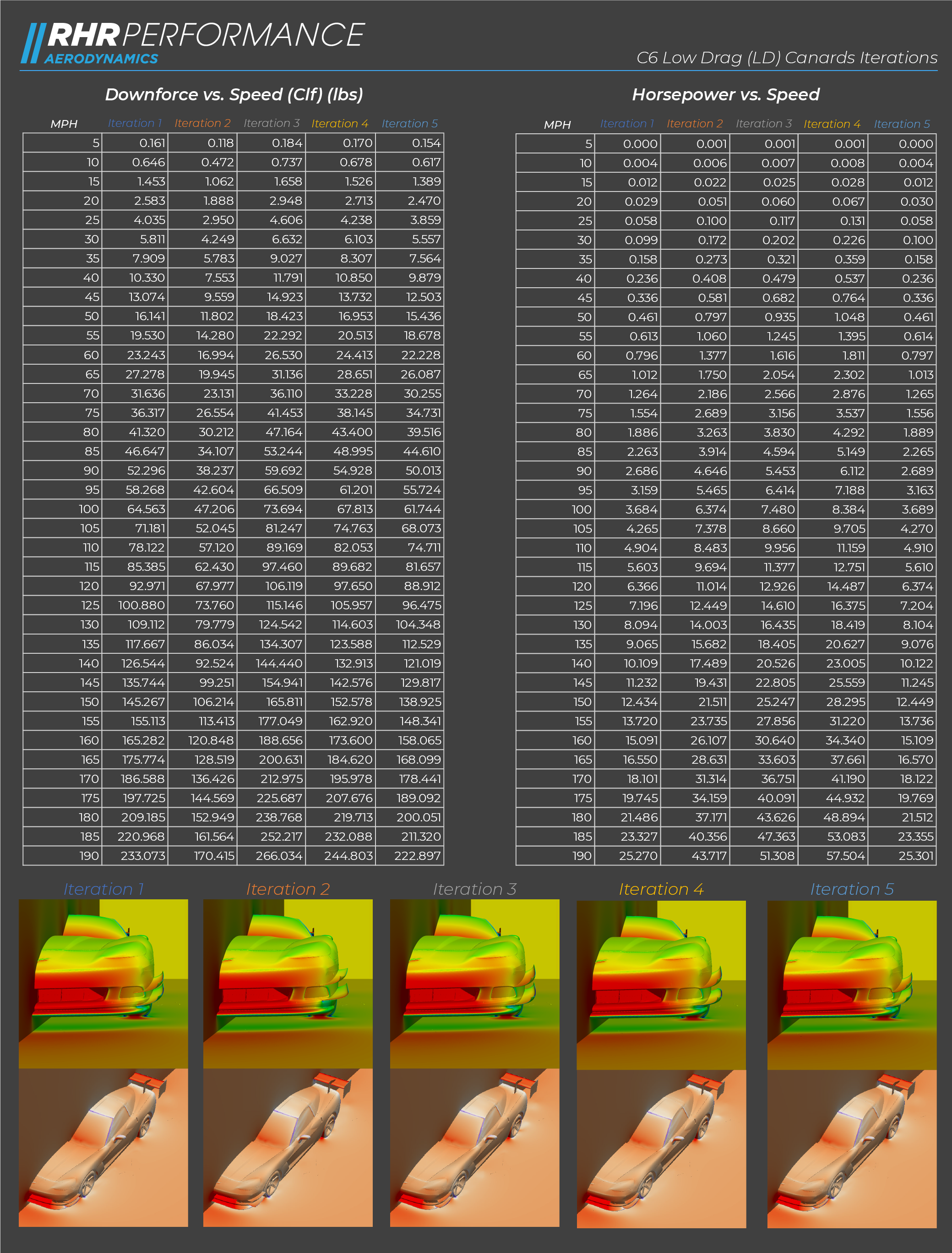
During the design process, each version (LD/HDF) underwent 5 design iterations and CFD passes. We used a static ride height of 2.5”, and for the LD versions a simple blade splitter and the Fulcrum single element wing, while the HDF versions had a more effective splitter and the Nike 17 dual element wing. In calculating the downforce and drag figures for the figure in these images, the splitter & wing contributions were subtracted from the coefficients. Some of the iterations made good downforce, but were very draggy, some didn’t make much downforce, but had very low drag. One HDF iteration made amazing downforce, but AJ shot down that iteration (HDF 4) because the aesthetics were too extreme in his option for the US market.
We picked HDF Iteration 2 and LD Iteration 5.
fig.2 HDF Iteration images
fig.3 HDF Iterations deltas
Our reasoning for choosing HDF 2 was (in Kyle’s words):
“it appeared that having the pressure peak earlier in iteration 2 kept it out of the high-pressure region of the splitter, keeping effective downforce high”
However, this comes with a rear downforce penalty (see the graph for Clr)- the lever arm effect of the downforce produced by the canard influences rear downforce- Archimedes’ lever is in effect here. We decided this was acceptable, as the raison d'être of the HDF set was “damn the drag, give me downforce”. Useful for short tracks, raining conditions, low grip tracks, or an abundance of horsepower.
fig.4 LD Iteration images
fig.5 LD Iterations deltas
LD 5 was chosen as it had the best Cd and L/D ratio of the 5 iterations. As a side note, and we’ll write more about this later, running CFD on the Corvette with LD 5 Canards installed, but the rearview mirrors removed effectively negated the additional drag of the canards AND provided a slight boost in Clr! Everything effects everything, as I love to say (I stole that from Neal Robert’s fantastic book).
I had mentioned previously that there are some corner cases where canards do more that augment a splitter, and the upper pair of the HDF set does just that. It’s placement (seemingly odd on the fender, right above the wheel arch) creates a suction effect that helps pulls air out of the wheel well. If you look at this GIF of the total pressure sliced though the car you’ll see the high-pressure air packed in the wheel well, and the air accelerating and the vortex forming under the fender canard.
fig.6 TP Slice Animation
fig.7 Velocity Slice illustrating the upper HDF canard and it's interaction with the wheel well
And it wouldn’t be RHR if we didn’t post more graphs, so here they are:
fig.8 HDF Iteration all data in graphical form
fig.9 HDF Iteration all data in table form
fig.10 LD Iteration all data in graphical form
fig.11 LD Iteration all data in table form
For a more general overview of why and how canards work, refer to this video by Dr. Kyle Foster:

