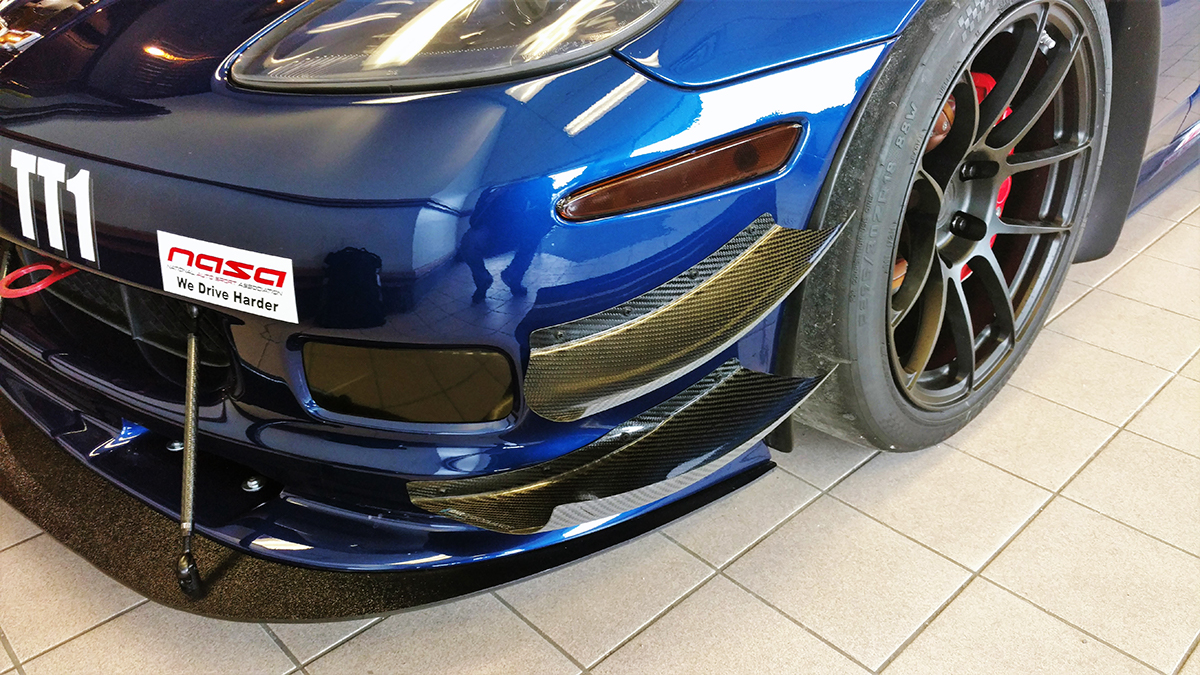
We’ve just shipped our first few sets of C6 Low Drag canards, and it’s been quite the process. Unlike our other recent project, Cardboard to Carbon this was more like CAD-CFD-Emails-CAD-Skype-CFD-CAD-Emails-CFD-Skype-CAD-STL export- import STL- Purchase 3D Print- Purchase bumper on eBay- Sanding- Chemicals- Glue, Dremel- Mold- to Carbon!
We started this design cycle in December of 2017 when AJ mentioned a recent number of calls he’d been getting about C6 canards. But, as he said, it’s expensive to purchase a C6 bumper. We then started to talk about how much downforce canards really make, and while we knew the answer was elusive, since it depends on many variables like splitter size, ride height, pitch, etc. We had some estimates based on some aerodynamic texts, but nothing definite for a product we carried, except for CFD on our wings, and data acquisition on our splitters.
As we were talking about spinning up RHR Performance, we decided from the onset that a key component of our strategy as a business in the aerodynamics market is to produce the best possible parts, full stop.
So, naturally we decided that since it was too expensive to buy a bumper, let’s spend A LOT more money and hire JKF Aero (AKA the Notorious Dr. Kyle), buy the 3D solid CAD model of a C6, buy a bumper, and then buy the 3D printed mock ups. This would solve the riddle of “how much downforce do these things make?” and produce a product that no one else could match.
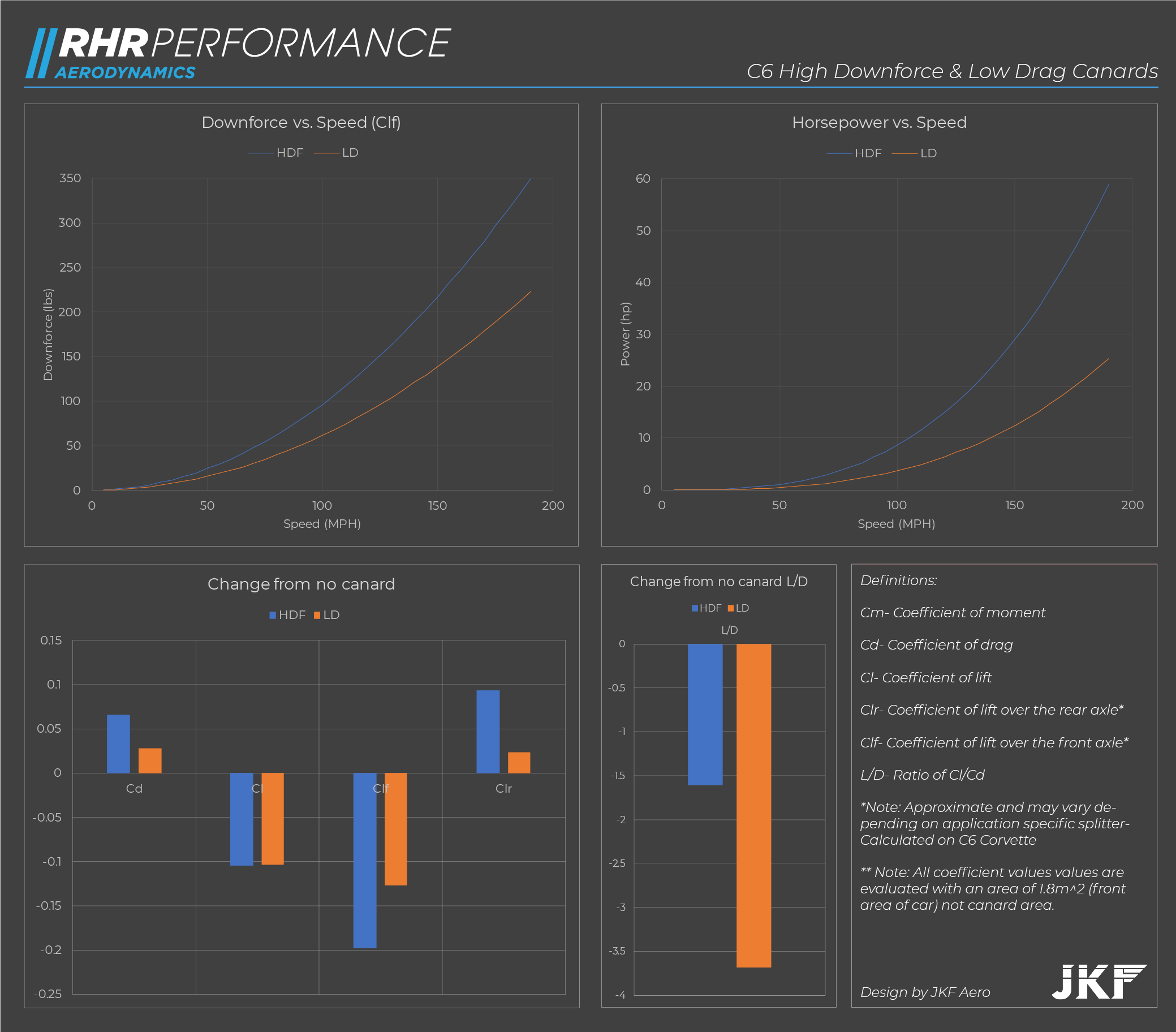
As we wrote about in this post here, we designed two sets (High Downforce, or HDF, and Low Drag, or LD). Each set underwent 10 iterations of CFD. The winners were then given back to us as 3D solid CAD models, along with a spreadsheet of data, a few hundred post processing screenshots, and some ancillary data files.
As a side note, Dr. Kyle looked at some “other canards” made a quick sketch of those base on some images found online, lined them up on the C6 model, ran them through CFD, and what did he find? A slight reduction in drag, and a tiny amount of lift. No downforce. Seriously- don’t bolt on triangular bits of carbon to the nose of your car and expect it to work. Ask for data.
What, no data?
Would you buy an engine without a dyno plot or HP/TQ figures?
I digress.
Great- so we have tons of data, CAD, a few hundred emails back and forth with Kyle, all we need to do now is make these simple shapes. Since we use Fusion360 for 3D CAD, extracting and thickening the faces was simple- while we need the actual canard to be razor thin (yet strong enough not to deflect at high speeds) the master plug needed to be thick and strong to serve as the basis for the mold. We chose a few different materials from Shapeways and had a few iterations printed and shipped.
Image- 3D Prints
AJ took some time and experimented with the various prints, picked the material he liked (a nylon-based hybrid material), then sanded it multiple times, sprayed with epoxy, gelcoat, some release agents, PBA; a complex mixture of chemicals that is more of an art than a science.
Image- Canard Mockup & Epoxy Coat
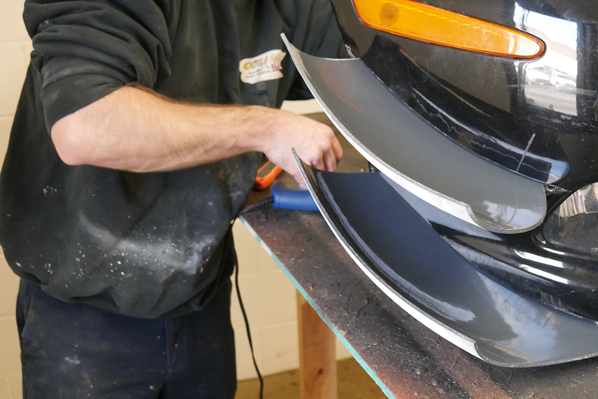
Since Dr. Kyle told us that the canard geometry was quite good and would prove to be re-usable on different cars in slightly different positions and angles, we over-printed the size (so the plugs may be re-used) and cut slots into the bumper to match up the intended design angle and depth.
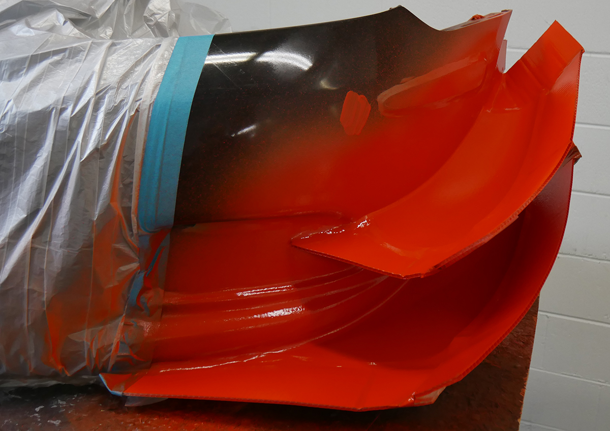
Image- Gelcoating the mold
Still, the process came down to taking the 3D prints, lining them up by hand, hand gluing the supports of the mold face and rear supports.
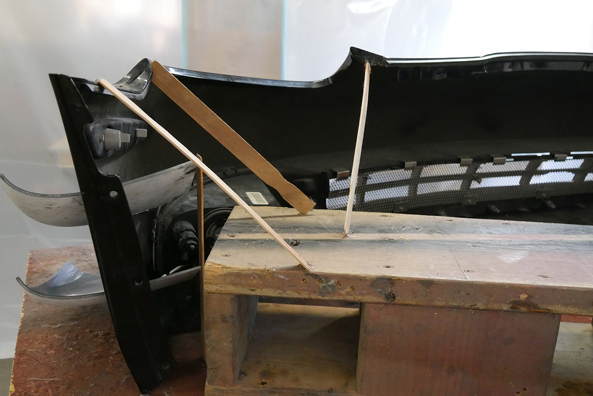
While our 3D models of the cars are high accurate, the modelers don’t bother with the geometry of the inside of the bumper for example, we had to be conscious of where the blinker light housing was located, where the strong points of the bumpers were placed, that sort of thing.
Image- Bracing the bumper w/ the latest in paint mixing technology
In the middle of this process we moved shops and re-launched as RHR Performance, so admittedly, this cycle from design to production took much longer than we had hoped.
Image- First set of canards in the wild!
We have a lot more coming in the next few months, so stay tuned- and reach out if you have any questions.
We’ve also put together a a video of the pressure & velocity slices; this modeled with a very small ZR1 style splitter, the LD canards, and our Fulcrum Wing.
Note: the most informative slice is the total pressure sequence. Total pressure is the static pressure + dynamic pressure- so it represents the energy of the flow, red indicates a freestream condition, thus no lost energy in the flow. Colors indicate that is something going on in the flow field, specifically the energy of the vortices.
Video- Pressure & Velocity Slices
If you'd like what you see, buy the canards!
Till next time,
The Team @ RHR
PS. Gotta post some data:
