If you follow this blog, or our other social media outlets (facebook and Instagram), you have seen our splitter tunnels that we released a little bit ago. We did an original blog post about splitters and tunnels that you can read here. The first handful of sets are out in the wild and all reports have been extremely positive. So we finally got around to putting together a video coupled with some CFD pictures and pressure slices to help explain how they work.
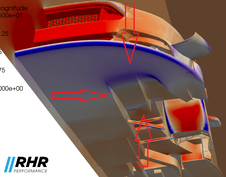
This screen grab of a CFD model quickly and easily shows the low pressure zone at the entrance of the tunnels.
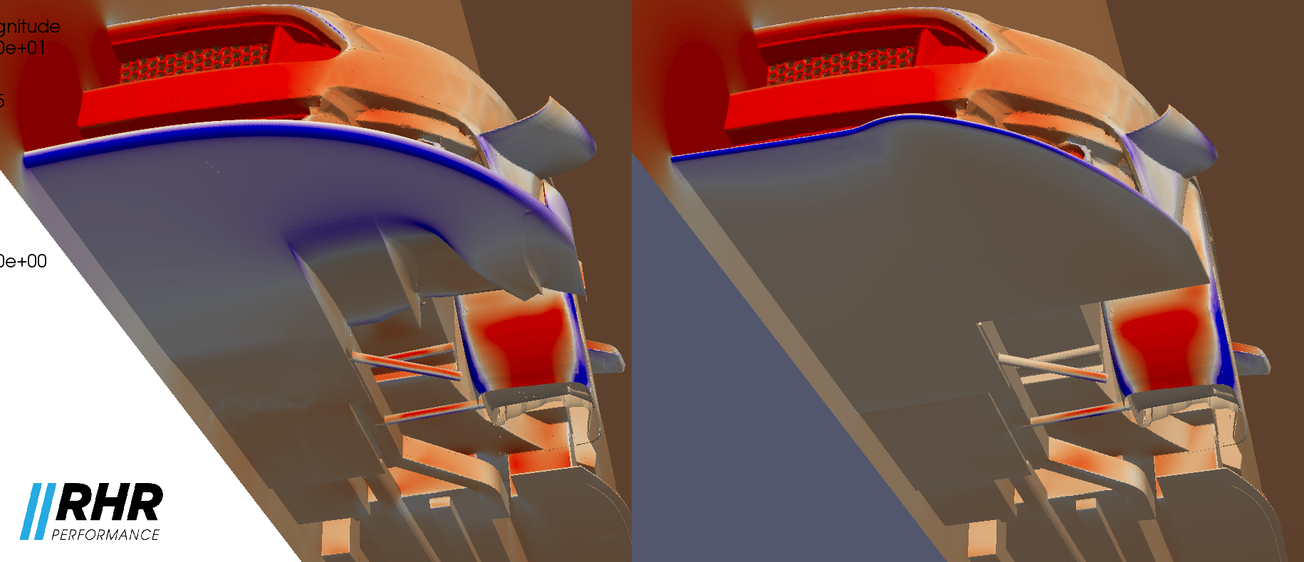
In this side by side shot you can easily see the extra size of the low pressure zone on the leading edge of the splitter, but you can also see a slightly lower (more blue-ish color) across just about the entire surface area of the flat part of the splitter.
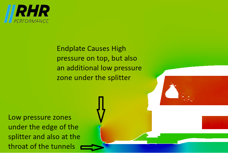
The last picture is of a pressure slice right around the entrance of the tunnels. This slice is from a model that had side plates, or end plates on the splitter. I make a quick mention of them in the video, but that will be a topic of its own.